
| Tweet |

Custom Search
|
|

|
||
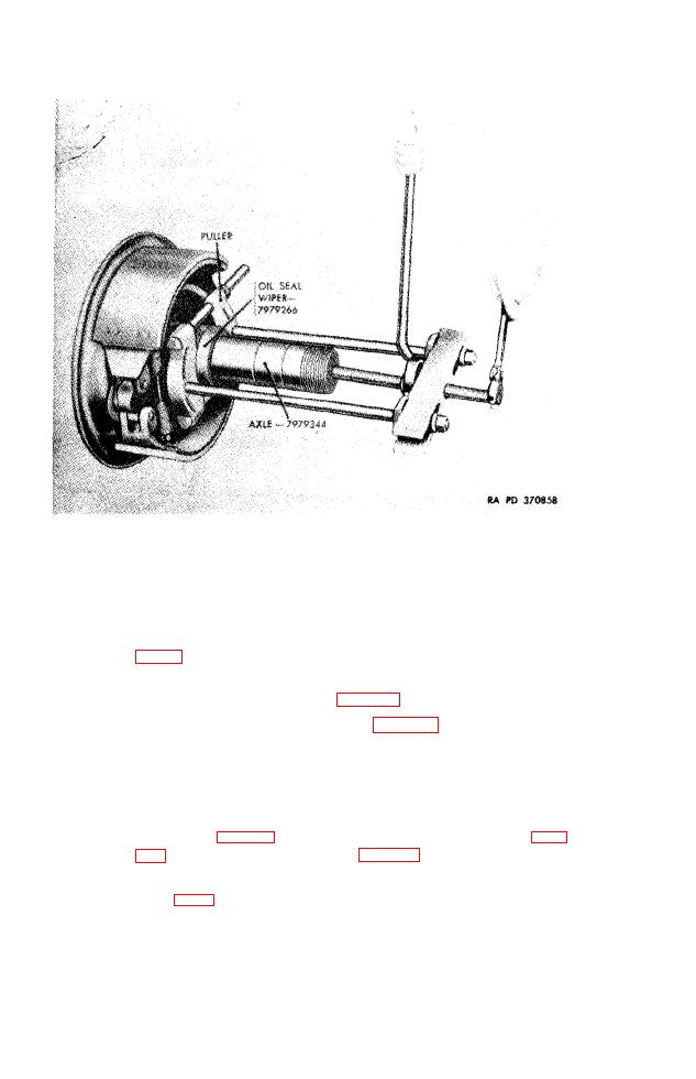 Figure 54. Removing oil seal wiper from axle using puller.
(a)
Position each backing plate with assembled shoes
and camshaft over axle spindle and against flange.
Aline holes in brake backing plate and flange of axle
and
install
and
peen
ten
9/18
x
15/8
rivets
(E,
fig. 59) .
(b)
Install spring bearing plates (par. 87a(3)).
(c)
Install slack adjusters (par. 64c).
(d)
Install
brake
air
chambers
63d).
g.
Installation.
(1) S e m i t r a i l e r
M270A1.
(a)
Move axle, with hydraulic dolly, into position. Lo-
cate
with
ends
of
each
spring
over
spring
bearing
57) . A t t a c h t o r q u e r o d s ( p a r . 8 8 d ) .
Position hydraulic lines leading to hydraulic lines
(b)
Secure
tee (fig. 41) on axle and connect to tee.
lines to axle with four cushioned clips, four No. 10
lockwashers, and four 1/4 x 1/2 cap screws.
(c)
Connect flexible hydraulic hose to tee and hydraulic
master
cylinder.
TAGO 1321B
124
|
||
|
||


