
| Tweet |

Custom Search
|
|

|
||
 TM 9-2330-380-14&P
4-23. Resistor Assembly (XM1063 Only) (cont'd)
3. Connect all disconnected wires and secure with screws (5) and nuts (4).
4. Using multimeter, check resistors for rated ohms marked on front of resistor (refer to wiring diagrams,
pages 4-58 and 4-59).
5. Position cover assembly (3) on resistor box and secure with 24 screws (1) and nuts (2).
Follow-on maintenance: None
This task covers:
a. Removal
b. Installation
Initial Setup:
Tools/Test Equipment:
EquipmentConditions:
General mechanic's tool kit (item 01, Appendix B)
Power source disconnected.
Materials/Supplies:
WARNING
Make sure all electrical power is disconnected before performing any maintenance on the electrical
system. Serious injury or death may result if proper precautions are not taken.
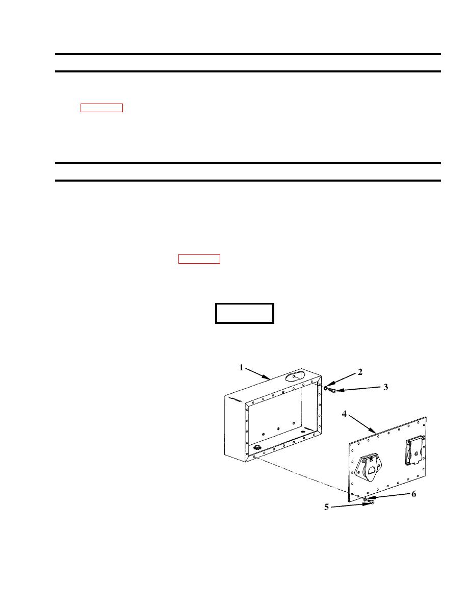
1. Remove 24 screws (5), washers (6)
and cover assembly (4).
2. Remove ten screws (3), washers (2)
andresistor box (1).
b. Installation
1. Position resistor box (1) and secure
with 10 screws (3) and washers (2).
2. Position cover assembly (4) and
secure with 24 screws (5) and
washers (6).
Follow-on maintenance: None
|
||
|
||


