
| Tweet |

Custom Search
|
|

|
||
 TM 9-2330-380-14&P
This task covers:
a. Removal
b. Inspection
c. Installation
Initial Setup:
Tools/Test Equipment:
EquipmentConditions:
Power source disconnected.
General mechanic's tool kit (item 01, Appendix B)
Materials/Supplies:
WARNING
Make sure all electrical power is disconnected before performing any maintenance on the electrical
system. Serious injury or death may result if proper precautions are not taken.
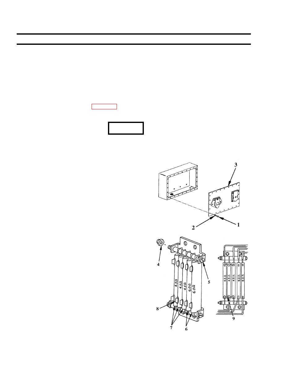
a. Removal
1. Make sure power source is disconnected and remove 24
screws (1) and washers (2) and cover assembly (3).
2. Remove two nuts (4) and screws (5) securing resistors
(6) and (7).
NOTE
The two 6-ohm resistors (6) can be removed separately.
The three 4.5 ohm resistors (7) are interconnected by jump
wires. Remove as a unit.
4. Tag and disconnect wires. Remove resistors..
b. Inspection
1. Check resistor contact points (8) for cleanliness. Clean
as required.
2. Using multimeter, check resistors for rated ohms marked
on front of resistor (refer to wiring diagrams, pages 4-
58 and 4-59).
3. Replace cracked, chipped or defective resistor.
c. Installation
1. Position 6-ohm resistor (6), connect wires and secure
with screws (5) and nuts (4).
2. Position 4.5-ohm resistors (7) and solder all jumper wire
(9) connections.
|
||
|
||


