
| Tweet |

Custom Search
|
|

|
||
 TM 9-2330-331-14&P
ABS BRAKE SENSOR AND POWER CONNECTION REPLACEMENT
INITIAL SETUP:
Equipment Conditions
Tools/Test Equipment
Ground Boards Emplaced
General Mechanic's Tool Kit (WP 0077 00-9)
Landing Legs Down
Tires Chocked
Materials/Parts
Semitrailer Disconnected from Prime Mover
Tiedown Strap, Nylon (0086 00-4)
Brake Drum Removed (WP 0036 00-1)
WARNING
Wear protective goggles when underneath semitrailer and opening
drain valve. Avoid air stream. Ensure all pressurized air has been
drained from system. Failure to do so could result in injury to personnel.
REMOVAL
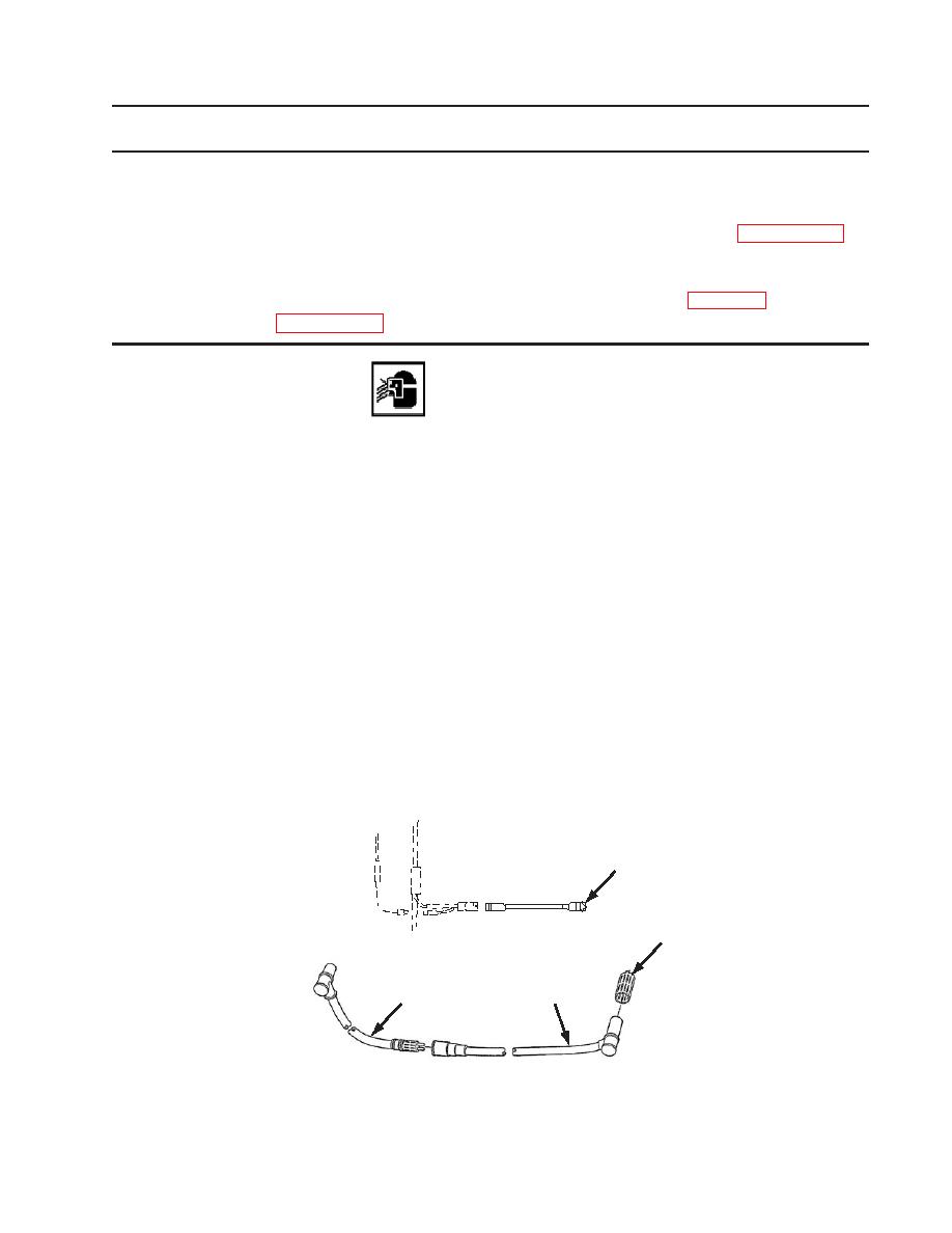
1. Remove ABS sensor (3) from sensor housing.
2. Remove retainer clip (2) from sensor housing.
3. Disconnect sensor cable (3) from sensor cable extension (4) and remove sensor cable (3) from wheel.
4. Disconnect sensor cable extension (4) from ECU valve.
NOTE
Complete step 5 only if replacement of ECU power cable is required.
5. Disconnect power cable (1) from ECU valve and power supply.
1
2
3
4
Figure 1. ABS Brake Power Connections
|
||
|
||


