
| Tweet |

Custom Search
|
|

|
||
 TM 9-2330-380-14&P
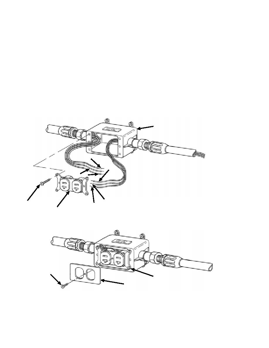
4. Connect the wires to the second connector receptacle (20). Insert the black wires (15) into the two holes
under the dark screws on one side of the receptacle and tighten screws until both wires are secure. Insert
the white wires (17) into the two holes under the light screws on the opposite side of the receptacle and
tighten screws until both of these wires are secure. Wrap the green wires (16) around the green grounding
screw protruding from the corner of the receptacle and tighten screw until both these wires are secure to the
receptacle (20).
5. Push the connector receptacle (20) into the electrical junction box (3) and fasten in place with the machine
screws provided with the receptacle (21).
6. Continue installing the remaining connector receptacles (20) in the same manner.
7. When completed, install the electrical wall plates (22) with the machine screws (23).
3
15
15
16 17
16
21
17
20
23
20
22
J-6
|
||
|
||


