
| Tweet |

Custom Search
|
|

|
||
 TM 9-2330-380-14&P
This task covers:
a. Removal
b. Inspection and repair
c. Installation
Initial Setup:
Tools/Test Equipment:
EquipmentConditions:
General mechanic's tool kit (item 01, Appendix B)
Materials/Supplies:
a. Removal
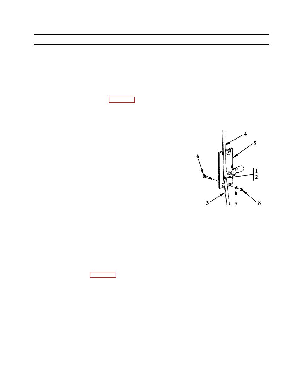
1. Remove shoulder screw (1) and spacer (2) securing center
locking rod (3) and upper locking rod (4) to upper lock
assembly (5).
NOTE
Upper locking rod will remain attached to upper slide bolt assembly.
2. Remove center locking rod (3).
3. Remove four bolts (6), washers (7) and nuts (8) and upper lock
assembly (5).
b. Inspection and repair
1. Inspect parts for cracks, bends, excessive wear and deterioration. Replace defective
parts.
2. Straighten locking rods to assure proper alignment in upper and lower bolt slide
fasteners. Replace defective parts.
3. Straighten bends or dents in slide bolt assembly covers that may cause binding. Replace
defective parts.
4. Check lock for ease of operation. Using grease fitting on handle lock assembly, lubricate
in accordance with Appendix I, Lubrication Instructions.
5. Clean and paint if necessary.
c. Installation
1. Position upper lock assembly (5). Secure with four bolts (6), washers (7) and nuts (8).
2. On upper lock assembly (5), position lower end of upper locking rod (4) with upper end
of center locking rod (3). Secure with shoulder screw (1) and spacer (2).
Follow-on maintenance: None
|
||
|
||


