
| Tweet |

Custom Search
|
|

|
||
 TM 9-2330-380-14&P
4-67. Interior Handle
This task covers:
a. Removal
b. Installation
Initial Setup:
Tools/Test Equipment:
EquipmentConditions:
General mechanic's tool kit (item 01, Appendix B)
Materials/Supplies:
a. Removal
NOTE
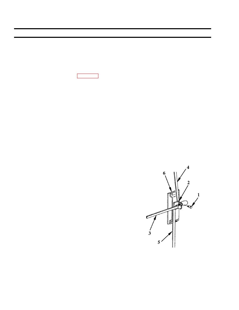
Center locking rod (4) will remain attached to upper lock assembly. Lower locking rod will remain
attached to lower slide bolt assembly.
Remove two shoulder screws (1) and spacers (2) securing interior
handle (3) and lower end of center locking rod (4) and upper end
lower locking rod (5) on lower lock assembly (6).
b. Installation
1. Position lower end of center locking rod (4) and upper end of
lower locking rod (5) with interior handle (3) on lower lock
assembly (6).
2. Secure handle and rods with two shoulder screws (1) and
spacers (2).
Follow-on maintenance: None
|
||
|
||


