| Tweet |

Custom Search
|
|

|
||
 TM 9-2330-331-14&P
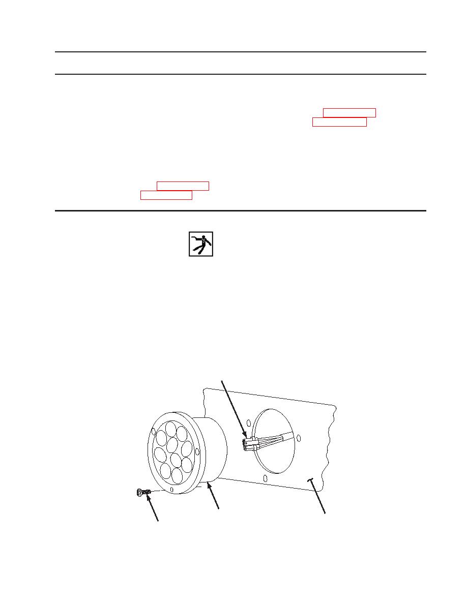
STOP, TAIL, AND DIRECTIONAL LIGHT REPLACEMENT
INITIAL SETUP:
Equipment Conditions
Materials/Parts
Ground Boards Emplaced
Self-Tapping Screws (WP 0080 00-1)
Landing Legs Down
Dielectric Grease (WP 0086 00-4)
Tires Chocked
Semitrailer Disconnected from Prime Mover
Prime Mover Electrical Connector
Disconnected from Semitrailer
TooIs/Test Equipment
General Mechanic's Tool Kit (WP 0077 00-9)
Common No. 1 Tool Kit (WP 0077 00-9)
REMOVAL
WARNING
When repairing an electrical malfunction, ALWAYS disconnect towing
vehicle electrical connector from semitrailer. Failure to do so may
result in serious injury or death due to electric shock.
NOTE
Right and left stop lights are removed and installed the same way. This
procedure covers one stop light.
1. Remove three self-tapping screws (4) and light body (3) from frame (2). Discard screws.
2. Unplug connector from wiring harness (1).
1
3
2
4
Figure 1. Stop, Tail, and Directional Light
|
||
 |
||