
| Tweet |

Custom Search
|
|

|
||
 TM 9-2330-330-14&P
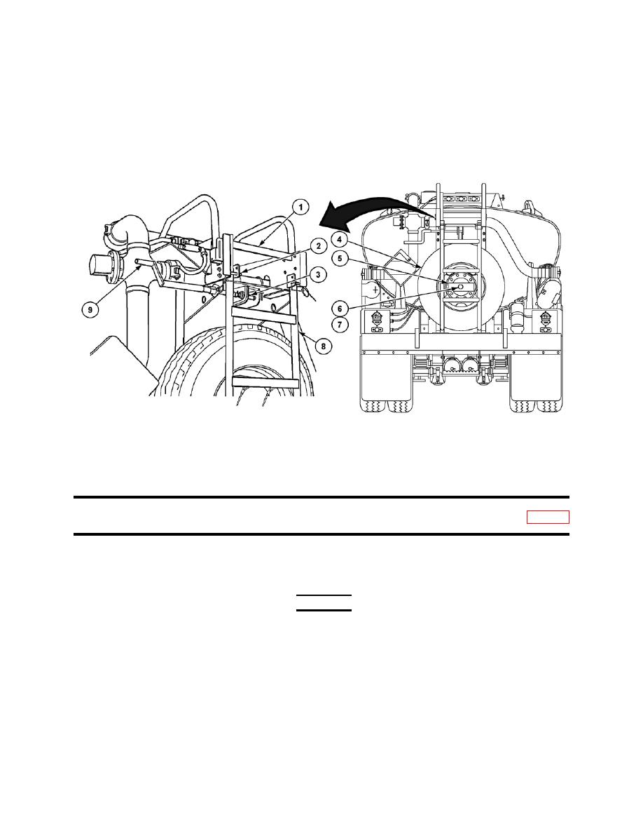
supported by cable (3).
3.
Carefully push spare tire (4) and ladder (8) in until resting against carrier assembly (1).
4.
Install two quick release pins (2) in ladder (8) and carrier assembly (1).
5.
Install reinforcement channel (5) to stud (7) with nut (6).
6.
Rotate winch handle (9) until cable (3) is tight and winch handle (9) is pointing down.
OPERATION UNDER USUAL CONDITIONS--Continued
J.
WHEEL ASSEMBLIES REPLACEMENT
Removal
WARNING
Replace wheel with semitrailer connected to prime
mover if possible. If semitrailer is not connected to
prime mover ensure that landing gear is lowered and
locked and wheels are chocked. Failure to follow this
warning may cause semitrailer to roll resulting in injury
to personnel or damage equipment.
NOTE
There are four wheel assemblies and they are replaced
the same way. This procedure covers one wheel assembly.
1.
Loosen but do not remove 10 nuts (2) while wheel assembly (1) is in contact with ground.
0007 00-37
|
||
|
||


