
| Tweet |

Custom Search
|
|

|
||
 TM 9-2320-279-10-3
Controls and Indicators (Cont)
2-91. LOCATION AND USE OF CONTROLS AND INDICATORS (CONT).
1
2
3
tfft00041p
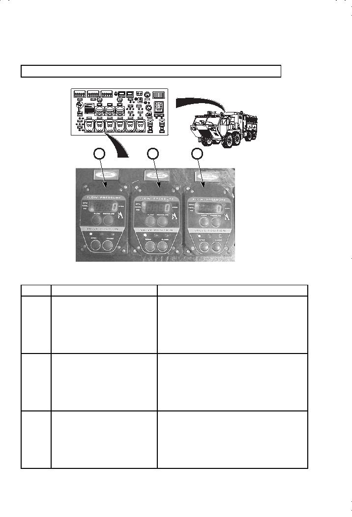
Figure 2-46. Pump Operator's Panel-Middle/Lower Left (Sheet 1 of 2).
Key
CONTROL OR INDICATOR
FUNCTION
1
NO. 1 DISCHARGE
Provides control of No.1 driver's side discharge.
(DRIVER SIDE) Electric Valve
Two button operation to read pressure, flow, and
Control/Meter
total flow. LED readout indicates GPM, total
gallons flowed, and psi. Two button, open and
close valve position capability with red (closed),
yellow (gated), and green (open) LED valve
position indicator lights.
2
NO. 2 DISCHARGE
Provides control of No. 2 driver's side discharge.
(DRIVER SIDE) Electric Valve
Two button operation to read pressure, flow, and
Control/Meter
total flow. LED readout indicates GPM, total
gallons flowed, and psi. Two button, open and
close valve position capability with red (closed),
yellow (gated), and green (open) LED valve
position indicator lights.
3
DRIVER PRE-CONNECT A
Provides control of driver's pre-connect A. Two
Electric Valve Control/Meter
button operation to read pressure, flow, and
total flow. LED readout indicates GPM, total
gallons flowed, and psi. Two button, open and
close valve position capability with red (closed),
yellow (gated), and green (open) LED valve
position indicator lights.
2-26
|
||
|
||


