
| Tweet |

Custom Search
|
|

|
||
 TM 9-2330-380-14&P
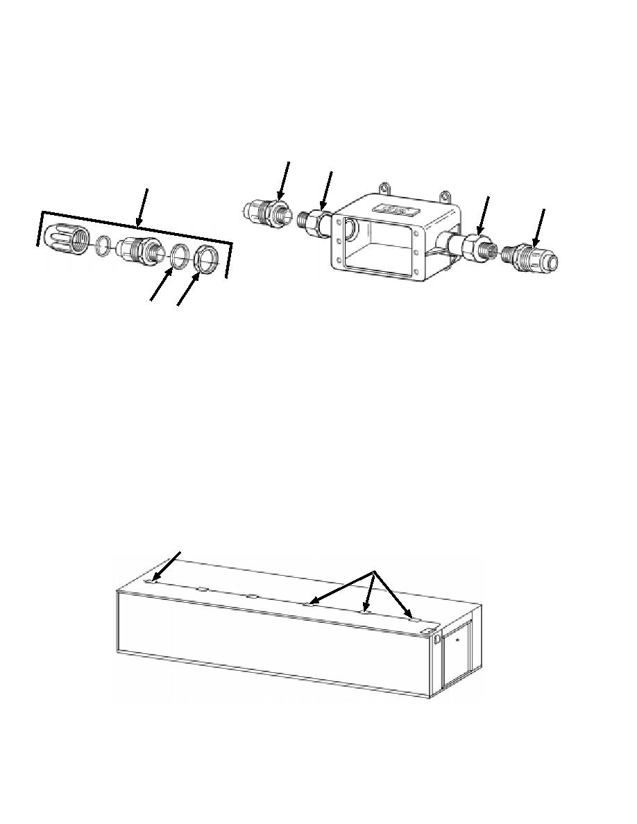
4. Disassemble the compression nut connectors, P/N LT43DN (5), prior to assembly. Discard the gasket (6),
and nut (7) on 11 of them. Keep the gasket (6) and nut (7) for the 12th one. Glue the straight ends of two
compression nut connectors, P/N LT43DN (5) on the ends of the female adapters, P/N E942D (4), previ-
ously installed. Ensure the glue does not adhere to the compression nut end. These will be used later in the
assembly.
5
4
5
4
5
6
7
B. ELECTRICAL JUNCTION BOX LAYOUT
1. Mark the locations of the junction boxes and install boxes with screws, P/N MS51861-67.
NOTE
The junction box with the single outlet, P/N E980DFN (3), is mounted as the last junction
box in the circuit, the farthest one from the circuit breaker box.
2. The illustration below is a guide only. Junction boxes can be installed in any location 110-volt power is
required depending on location of desks, workbenches etc. The amount of PVC electrical conduit may vary
depending on the exact location for the junction boxes. Ensure enough conduit is on hand prior to installa-
tion.
3
Typicalelectricaljunctionboxlocations
J-2
|
||
|
||


