| Tweet |

Custom Search
|
|

|
||
 TM 9-2330-380-14&P
4-92. Loading Procedure (XM1063 Only) (cont'd)
c. Loading procedures
NOTE
When removing or installing self-locking nuts, one person holds the nut stationary while the
other person turns the screw or bolt.
Do not remove five screws on each side of dolly that attach dolly to van body until instructed
to do so.
1. Working as a team, loosen five screws on each side of dolly that attach dolly to van body.
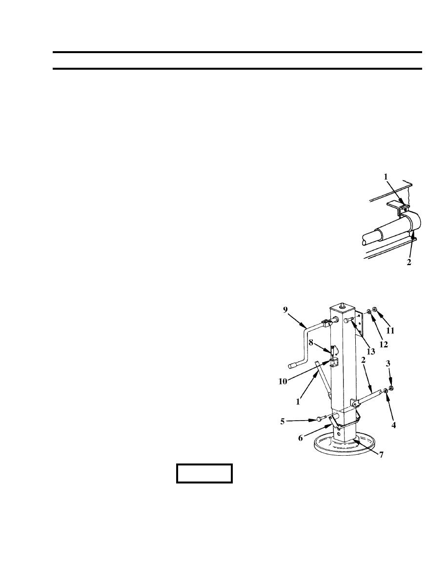
2. Disconnect electrical connector on left side of dolly by pulling up snap lock tab (1)
to release locking clamp (2). Pull connector from plug.
3. Stow removed connector in locking clamp on dolly left side rail. Close snap lock.
4. Disconnect front and rear brake lines by pulling back quick disconnect coupling
collar. Pull apart the connecting brake lines. Stow dolly portion of line inside dolly rail.
NOTE
When removing or installing self-locking nuts, one person
holds the nut stationary while the other person turns the
screw or bolt.
5. Working as a team, remove leveling jack braces (1 &
2) by removing nuts (3), washers (4) and screws (5)
securing braces to mounting bracket at top and to
lower jack leg at the bottom. Install hardware
removed from top of braces in holes in mounting
bracket. Install hardware removed from bottom of
braces in holes at bottom of leg.
6. Lift release handle (6) on leveling jack to release drop
leg (7). Lower drop leg to lowest position before
contacting ground. Return handle to locked position.
7. Release pin (8) securing each crank (9) in stowage
bracket (10) on leg. Place crank in operating position.
Turn each clockwise until bottom of drop leg (7)
contacts ground to support leg only, not van body.
Return crank to stowed position and secure with pin
(8).
WARNING
Leveling jack is heavy. Two persons are required to remove/install leveling jack.
8. Working as a team, remove six nuts (11), washers (12) and screws (13) attaching each jack to
mounting bracket. Stow hardware in holes in brackets hardware was removed from.
4-141
|
||
 |
||