
| Tweet |

Custom Search
|
|

|
||
 TM 9-2330-380-14&P
4-51. Slack Adjuster (M129A4 Only) (cont'd)
e . Adjustment
NOTE
M129A4 slack adjusters are self-adjusting. Use this procedure when installing new slack adjusters or
when slack adjusters have been disconnected.
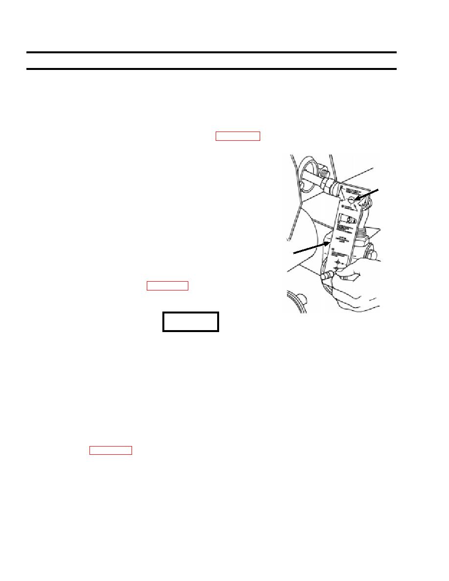
Fabricate clevis installation gage using template in Appendix G.
1. Place clevis installation gage (11) so it fits over pin body in air
chamber shaft (8).
2. If slack adjuster is properly adjusted, a pencil can be placed
8
into the center of the air chamber shaft and 6.0 hole in gage.
NOTE
If measurement is more than 6.0, move inner nut up air
chamber shaft. If measurement is less than 6.0, move inner
nut down air chamber shaft.
11
3. If proper measurement is not present, remove slack adjuster
and adjust inner nut as required.
4. Lubricate in accordance with Appendix I, Lubrication
Instructions.
WARNING
Ensure brake drum moves freely after completing step 5 (backing off adjusting screw (4) 3/4 turn).
Brake drum should move freely. Failure to do so could result in damage to equipment and serious
injury to personnel.
5. Turn adjusting screw (4) clockwise until brake drum does not move. Back off adjusting screw (4) 3/4
turn. Brake drum should move freely.
Follow-on maintenance:
Install dust cover.
Uncage brakes (para. 2-27).
4-90
|
||
|
||


