
| Tweet |

Custom Search
|
|

|
||
 TM 9-2330-380-14&P
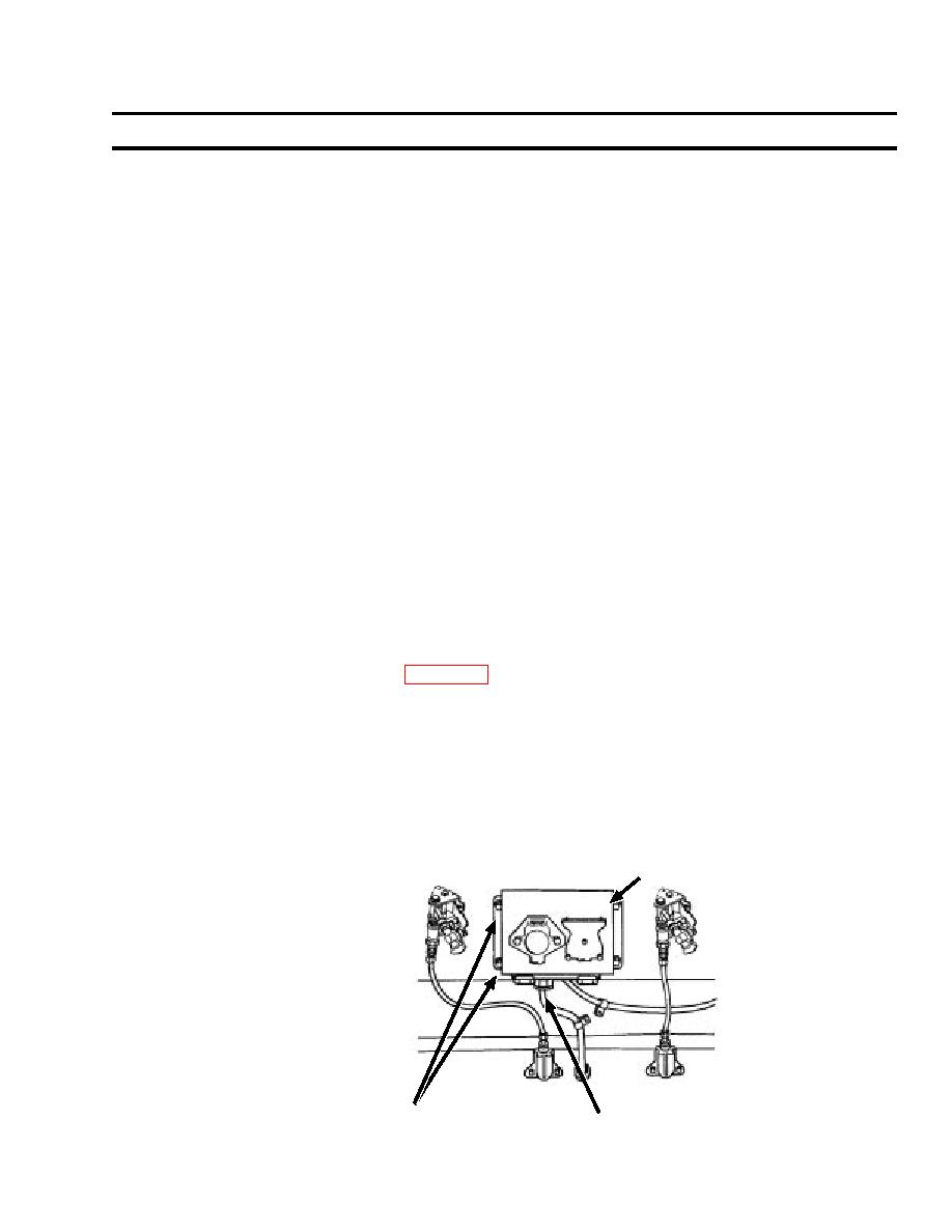
4-26. Voltage Converter Box (Including M129A4 with LED Lighting System) (cont'd)
(k) If damaged, remove grommet (30) from converter box (4). Discard screw and clamp.
(l) If damaged, remove screw (28) securing clamp (29) to converter box (4). Discard grommet.
(m) If damaged, remove gasket (31) from converter box (4). Discard gasket.
(n) Replace deffective converter box (4).
(o) If gasket (31) was removed, make sure surface area of converter box cover (4) is clean.
(p) Remove paper backing from new gasket (31) and install on converter box cover (4).
(q) If grommet (31) was removed, install new grommet in converter box (4).
(r) If clamp (29) was removed, install new clamp (29) and screw (28) on converter box (4).
(s) If coupling (27) was removed, install new coupling (27) in converter box (4) using new o-ring (26)
and nut (25).
(t) If terminal board (9) was removed, position new terminal board (9) in converter box (4) and secure
with four screws (23) and new selflocking nuts (24).
(u) Install connector (22) in converter box (4). Secure with two bolts (19), nuts (21), and new
lockwashers (20).
(v) Install connector (18) in converter box (4). Secure with four screws (15), nuts (17), and new
lockwashers (16).
(w) Install wires (8) through coupling (27).
(x) Install wires (7) through grommet (31).
NOTE
Refer to wiring diagram on page 4-66 and previously tagged wires prior to installing wires
to terminal board and grown stud.
(y) Install two ground wires (10) on ground stud (11). Secure with new lockwasher (14) and
selflocking nut (13).
(z) Position wires (5),(6),(7), and (8) on terminal board (9) and secure with fourteen screws (12).
e. Installation
1. Position voltage converter box (4) and secure with four new lockwashers (3) and screws (2).
2. Connect wiring nut (1).
4
Follow on Maintenance: None
2,3
1
4-37
|
||
|
||


