
| Tweet |

Custom Search
|
|

|
||
 TM 9-2330-326-14&P
b. Site Preparation:
1. Grind the area of the bolster plate (5), where the new kingpin mushroom will sit, flush so the new
kingpin will lie flat on the bolster plate.
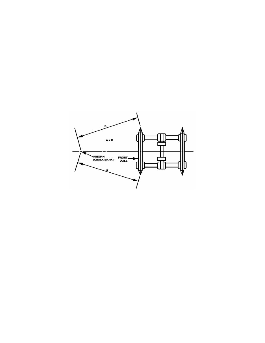
2. Position new kingpin (4) on bolster plate (5).
3. Drop a plumb line with bob from the kingpin (4) to ground and mark spot with a chalk mark.
4. To center the kingpin (4), measure the distance from the chalk mark to the center of the hubcap on
the front axle (A and B). The difference between measurements should be no more than 3/8 inch.
This measurement is for kingpin positioning and is not to be confused with axle alignment
procedures and specifications, which have closer tolerances.
5.
If the measurements are not correct, adjust position of kingpin (4) on bolster plate (5) until
measurements are within limits.
c.
Welding:
1. Weld the kingpin (4) mushroom to the bolster plate (5) with a continuous 5/8 inch fillet weld. Welds
are to be in accordance with MIL-STD- 1261, class 3. Use 70,000 psi electrode or wire of the
following specifications: electrodes, mineral coated, low hydrogen, MIL-E_2200/6 type MIL-10015 or
MIL-10016. Wire, use bare solid wire, and low alloy steel, MIL-E-23765/2 type 100S-1 or 110S-1.
2. Repeat step 6 two times to obtain a continuous 3-pass weld on the kingpin.
3. Inspect kingpin weld and the air-arc cut edges with dye penetrate or magnetic particle inspection.
No cracks are allowable. Any cracks found must be ground out or otherwise repaired.
4. Weld into place the brace bar (6) initially removed from the over the kingpin. Weld each end to
crossmembers (7) and the full length of the bar over the kingpin (4) and bolster plate (5).
7-19
|
||
|
||


