TM 10-4930-251-12&P
a. Removal.
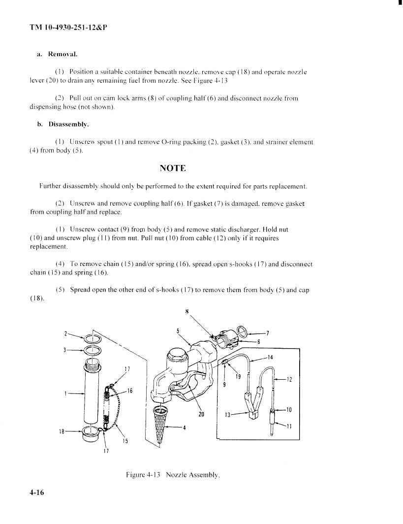
(1) Position
a suitable
container
beneathnozzle.removecap(18) andoperatenozzle
lever (20) to drain any\,remaining
fuel frorn nozzle. See Figure 4- 13
(2)
Pull out onlcam lock arms (8) of coupling half(6)
and disconnect nozzle from
dispensing
hose (not shown).
b.
Disassembly.
1)
Unscrew Spout ( 1) and remove O-ring, packing
(2), gasket (3). and strainer element
(4) from body (5).
NOTE
Further disassembly should only be performed to the extent required for parts replacement.
(2)
Unscrew and remove coupling half (6). If gasket (7) is damaged. remove gasket
from coupling
half and replace.
( 1)
Unscrew contact (9) fromi body (5) and remove static discharger. Hold nut
10) and unscrew Plug ( 11 ) from nut. Pull nut ( 10) from cable ( 12) only if it requires
replacement.
(4)
To remove chain ( 15) and/or spring ( 16), spread open s-hooks ( 17) and disconnect
chain
15) and spring ( 16).
(5)
Spread open the other end of s-hooks
(17)to remove them from body (5) and cap
8
5
7
6
14
17
19
16
9
12
10
0
13
4
11
15
17
Figure 4-13
Nozzle Assembly
4-16
|
|