TM lo-1930-251-12&P
DISPEliS
N O Z Z L E
G R O U N D .
N OZk’lE
GZOUrJD
F L U G
h
VEHiCLE
F U E L T A N K
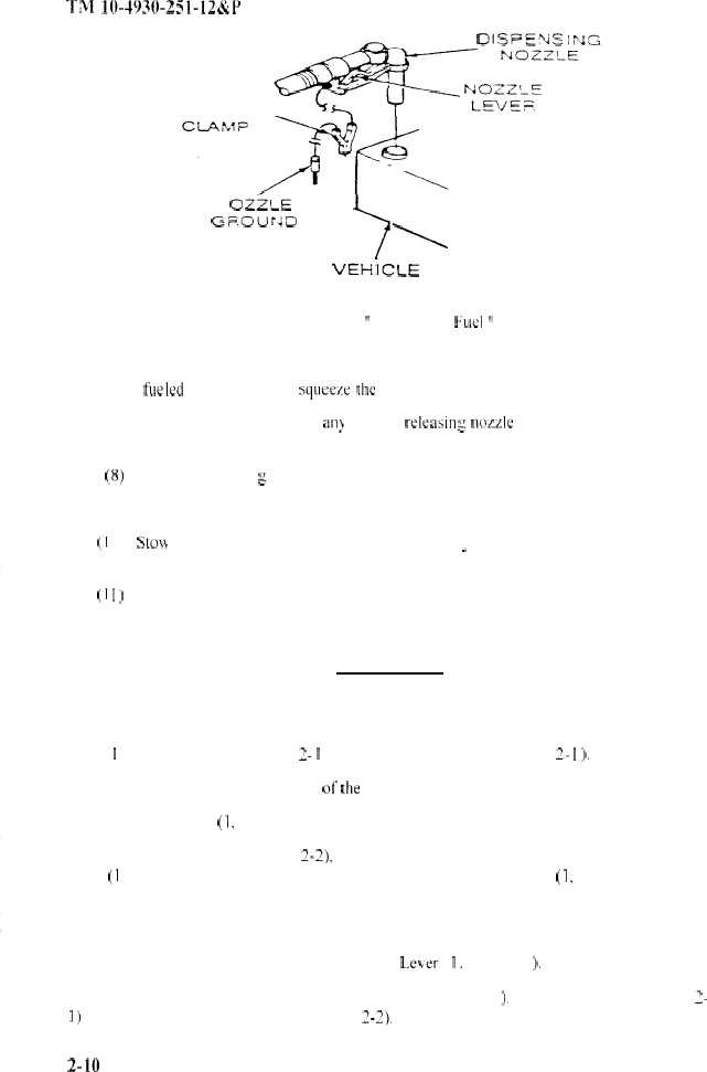
Figure 2-9
” Dispensing Fuel ”
(6) Place control lever (5. Figure 2-5) in “open” position. Insert dispensing nozzle into
tank being fileled (Figure 3-9) and squeex the nozzle lever. Dispense liquid.
(7)
The flow may be stopped at any time by releasin g nor.zle lever. thus closing nozzle
When tank is full. dispensing is complete.
(8) Remove dispensin g nozzle from tank. disconnect nozzle ground clamp or plug.
.
(9) Place control lever in “Closed” position.
(I 0)
Sto\v the hose (5, Figure 2-8) and nozzle assemblv (6. Figure 2-8) and cap the bottom
i
loading valve port (2. Figure 2-7) with dust cap as depicted.
(I I )
Load safety equipment. Disconnect static ground rod as per paragraph 2-8
c. Draining the Tank.
WARNING
Do not drain petroleum products or
flammable liquids on transporting equipment or the ground!
( I )
Connect hose (8, Figure 2- I ) to bottom loading valve (3. Figure 2- I ).
(2)
Position hose over the side ofthe trailer into suitable drainage container.
(3)
Open Lever (I, Figure 2-l ) and drain tank.
(4)
Connect hose (5. Figure 2-2), without nozzle (6, Figure 2-2) to bottom loading
valve (I 2, Figure 2-2): th’IS will allow you to drain frorn tank Open Lever (I, Figure 2-l ) and
drain tank.
(5)
Direct draining product into suitable container for storage or disposal.
(6)
When tank is completely drained. close L,e\er ( I. Figure 2-l ).
(7)
Disconnect Hose (5. Figure 2-2) or Hose (8. Figure 2-l ). Reconnect Hose (8. Figure 3-
I) to Fuel Manifold or stow Hose (5. Figure 2-2).
2-10
|
|


