TM 10-3930-665-13&P
CHAPTER 2
OPERATING INSTRUCTIONS
Section I Description and Use of Operator Controls
2-1 CONTROLS
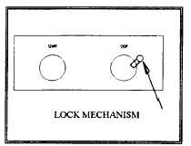
Once the machine is in position, and all adjustment mechanisms are properly locked, the conveyor may be plugged in, and
operation may begin. The start switch (Figure 2-1) at either end of the unit can be used to start the conveyor, and the
conveyor can be stopped by pressing either stop switch.
Figure 2-1.
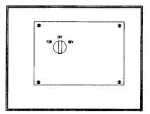
Figure 2-2.
Locking either stop button with the attached lock mechanism will make the conveyor inoperative.
The main operator control panel (Figure 2-2) contains the directional selector switch. This switch is used to change the
direction of the belt movement. It is a three position switch, forward, off, reverse.
CAUTION:
THE DIRECTION OF THE BELT CANNOT BE CHANGED WHILE THE CONVEYOR IS
IN MOTION. FAILURE TO DO SO MAY CAUSE EQUIPMENT DAMAGE.
2-2 LIFTER
The incline of the belt conveyor is adjusted using a hand wheel which is mounted to the lower frame. Clockwise rotation
raises the conveyor, and counter-clockwise rotation lowers it.
CAUTION:
ENSURE LOCKING PINS ARE REMOVED BEFORE RAISING OR LOWERING THE
CONVEYOR. FAILURE TO DO SO MAY CAUSE EQUIPMENT DAMAGE.
2-1
|
|