
| Tweet |

Custom Search
|
|

|
||
 TB 9-2330-336-14
INSTALLATION (continued)
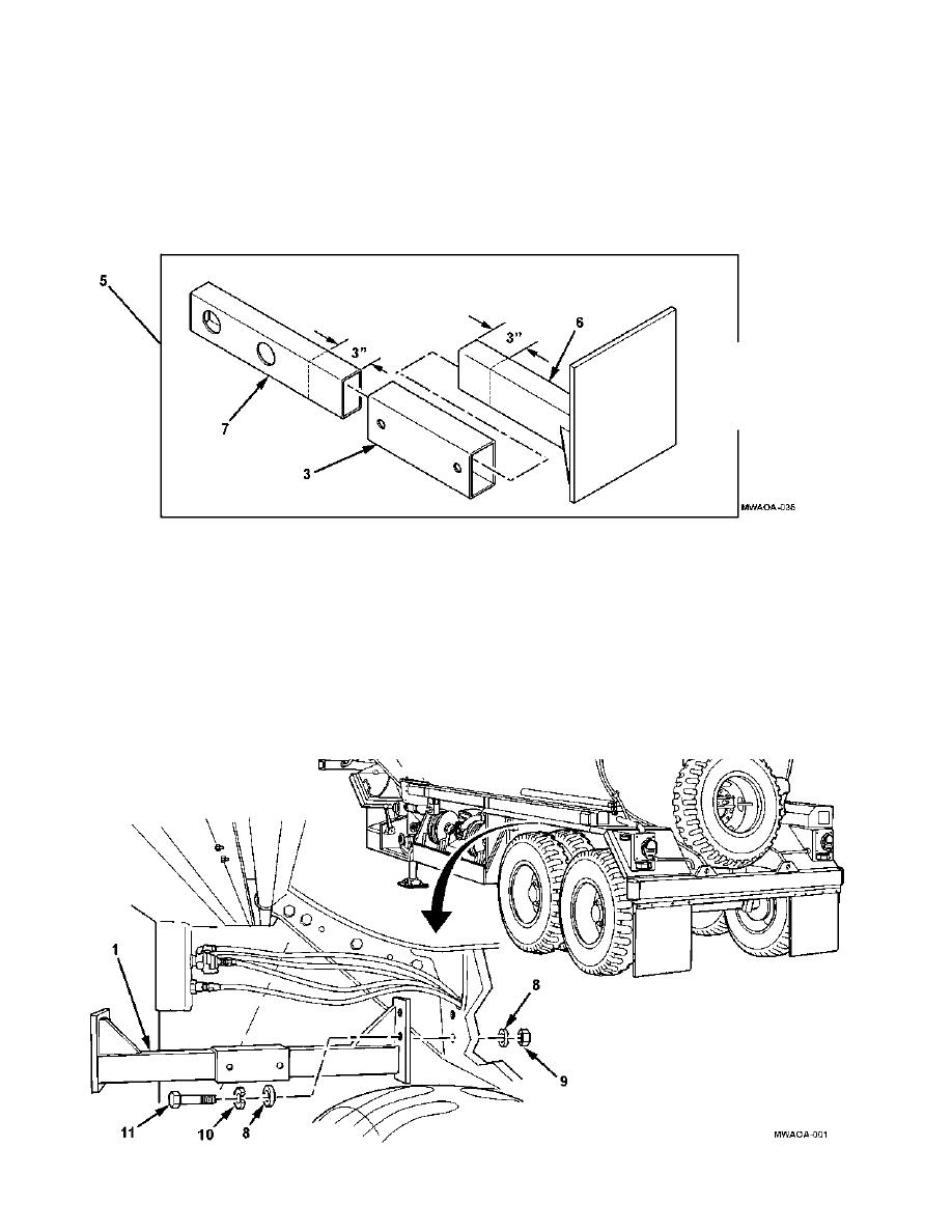
3. Scribe a locating mark 3 inches (8 cm) from end of support bracket (7) and support bracket (6), as shown.
These marks will be used to position the slider support bracket (3).
4. Assemble left rear bracket assembly (5) using support bracket (7), support bracket (6), and slider support
bracket (3), as shown.
NOTE
If the through holes are not found on vehicle frame, use the left front bracket (1) as
a template and drill using a 19/32- inch drill bit.
5. Locate two existing holes through vehicle frame as shown.
6. Install left front bracket assembly (1) on vehicle frame with four flat washers (8), two hexagon head
capscrews (11), lockwashers (10), and self-locking nuts (9), as shown. Torque self-locking nuts to
55-65 lb-ft (75- 81 Nm).
4-4
|
||
|
||


