
| Tweet |

Custom Search
|
|

|
||
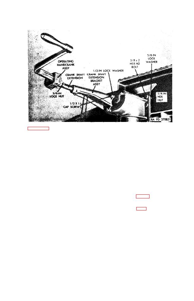 assembly-installed.
sting
handcrank
assembly to crank shaft extension ex-
tending
from
crank
shaft
extension
bracket
assembly.
Handcrank
assembly
will drop off extension.
Remove
three
cap
screws
and
which
se-
(2)
cure crank shaft extension bracket assembly to gear
box of right leg assembly of landing gear. Slide crank
shaft
extension
bracket
assembly
outward
and
remove
crank shaft extension bracket assembly and handcrank
shaft
extension.
b.
Removal
of
Landing
Gear
Leg
(1)
Lift
front
end
of
semitrailer
with
jacks
and
block.
Block
wheels,
using
chock
blocks
14)
to
pre-
vent
movement
of
semitrailer.
(2) If leg assemblies of semitrailer M270A1 are being re-
moved, remove two hex nuts and two lockwashers from
each
U-bolt
assembly
which
secures
lower
portion
of
upper leg to bracket welded to chassis frame and re-
move
U-bolt
assembly.
If leg assemblies of semitrailer
M270
or
M269
are
being
removed,
remove
two
hex
nuts,
two
hex-head
bolts,
and
two
lockwashers
which
secure lower portion of each upper leg to bracket welded
to chassis frame.
(3) Remove two hex-head bolts and locknuts which secure
crank
shaft
coupling
to
end
of
crank
shaft
extending
TAGO 1321B
105
|
||
|
||


