
| Tweet |

Custom Search
|
|

|
||
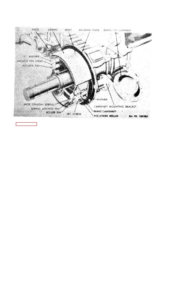 brake
drums
and
are
supported
by
the
brake
back
ing plates which are riveted to flanges on the axles.
Brake
camshaft
mounting
brackets,
riveted
to
the
backs of the brake backing plates, carry the brake
camshafts on needle bearings.
Each wheel brake mechanism has two brake shoes,
(b)
the
outer
surfaces
of
which
are
fitted
with
brake
linings riveted to the shoes. Each shoe is anchored
at one end on an (eccentric) anchor pin on which
it pivots. The other end of each shoe is free to be
pressed
outwardly
or
pulled
inwardly.
An S-shaped cam, on the end of the camshaft, is
(c)
mounted between the free ends of the two shoes.
Rotation
of
the
cam
forces
the
shoes
outwardly
to
apply the brake linings to the drum.
(d)
A shoe tension spring, hooked on spring anchor pins
near the free ends of the brake shoes, retracts the
shoes from the drum and holds them in retracted or
released
position.
The free ends of the shoes are fitted with (cam)
(e)
follower rollers which bear on the S-shaped cam. The
contour of the cam is so designed that the positions
of
the
brake
shoes
with
relation
to
the
drum
are
determined by the points on which the cam follower
TAGO 1321B
28
|
||
|
||


