
| Tweet |

Custom Search
|
|

|
||
 TM 9-2330-380-14&P
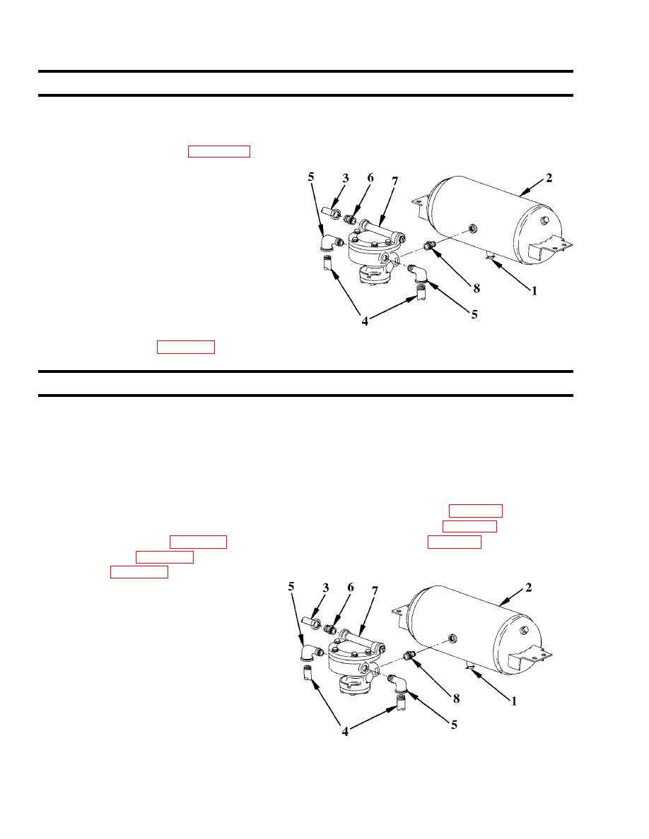
4-43. Front Relay Valve (cont'd)
f. Installation
NOTE
Apply teflon tape (item 12, Appendix E) to threads of air line connections before installation.
1. Install nipple (8) at rear of relay valve.
2. Install relay valve to reservoir by turning entire
assembly clockwise.
3. Install two elbows (5) and two male connectors
(6).
4. Connect input line (3) and output lines (4) to
elbows (5) and connectors (6).
5. Close all drain cocks (1) and pressurize air
brake system.
6. Check for leaks (para. 4-39b).
This task covers:
a. Removal
b. Cleaning and inspection
c. Installation
Initial Setup:
Tools/Test Equipment:
EquipmentConditions:
Operating test performed (para. 4-43a).
Materials/ Supplies:
Leakage test performed (para. 4-43b).
Drycleaningsolvent(item3,AppendixE)
All drain cocks open (para. 4-46).
Teflon tape (item 12, Appendix E)
Brush (item 15, Appendix E)
a. Removal
1. Disconnect input line (3) from male
connector (6) and two output lines (4)
from elbows (5).
2. Remove two elbows (5) and male
connector (6).
3. Remove relay valve (7) by turning
entire valve assembly counterclockwise.
4. Remove nipple (8).
4-70
|
||
|
||


