
| Tweet |

Custom Search
|
|

|
||
 TM 9-2330-331-14&P
0033 00
MAIN WIRING HARNESS REPLACEMENT
MAIN WIRING HARNESS REMOVAL
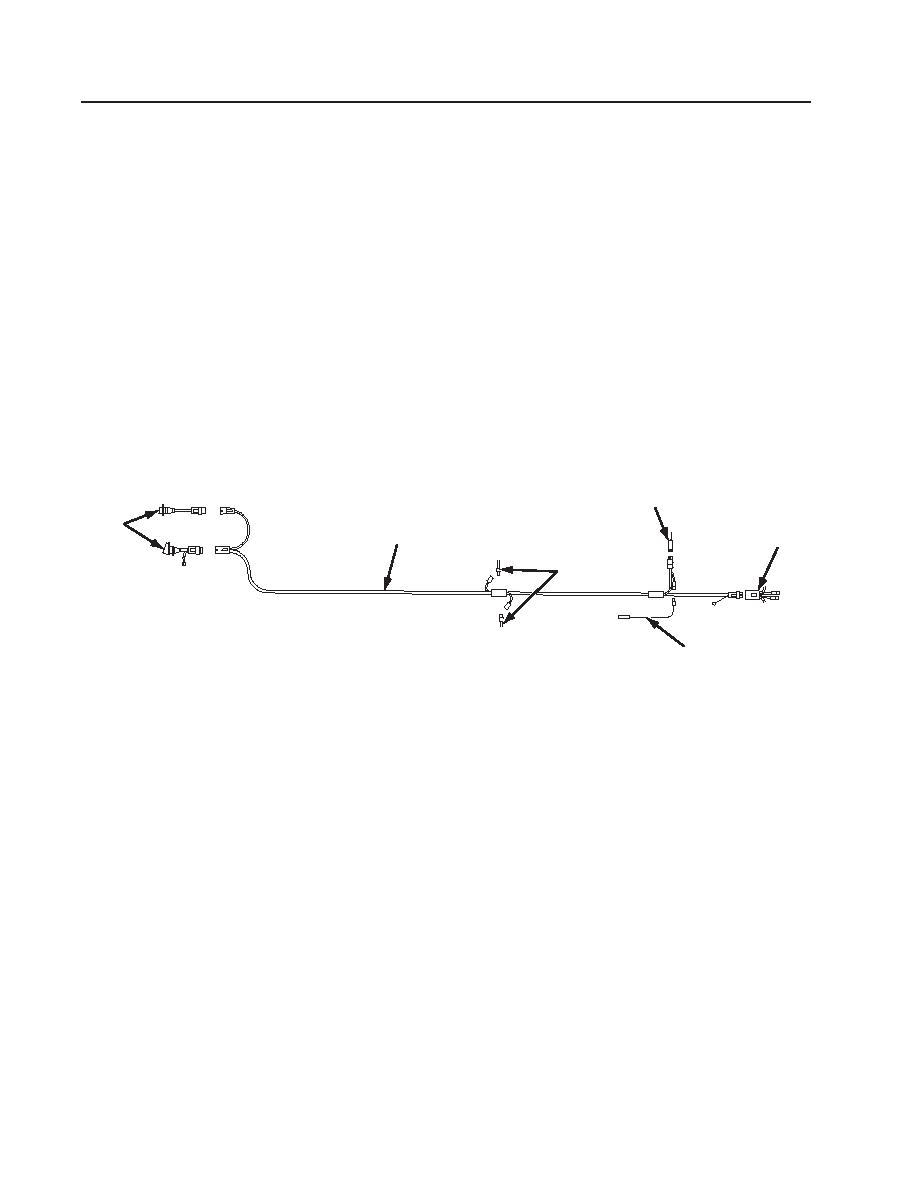
1. Disconnect main wiring harness (2) from 12 and 24-volt electrical receptacles (1).
2. Disconnect main wiring harness (2) from side clearance light harness (3) and rear wiring harness (5).
3. Disconnect main wiring harness (2) from ABS ECU power cable (4) and ABS warning light indicator
cable (6).
4. Remove main wiring harness (2).
5. Remove and discard damaged grommets as necessary.
MAIN WIRING HARNESS INSTALLATION
1. Install new grommets as needed.
2. Install main wiring harness (2) to frame.
4
1
2
5
3
6
Figure 2. Main Wiring Harness
NOTE
See charts in WP 0025 00-3 for details on wiring diagram.
Apply dielectric grease to each plug before connecting to other cables
and harnesses.
3. Connect main wiring harness (2) to ABS ECU power cable (4) and ABS warning light indicator cable (6).
4. Connect main wiring harness (2) to side clearance light harness (3) and rear wiring harness (5).
5. Connect main wiring harness (2) to 12 and 24-volt electrical receptacles (1).
6. Connect to prime mover and check all lights for correct operation.
0033 00-2
|
||
|
||


