
| Tweet |

Custom Search
|
|

|
||
 TM 9-2330-330-14&P
FLANGE AND PIPING MANIFOLDS, HANDWHEELS, AND
0132 00
F, E, AND B VALVES REPLACEMENT
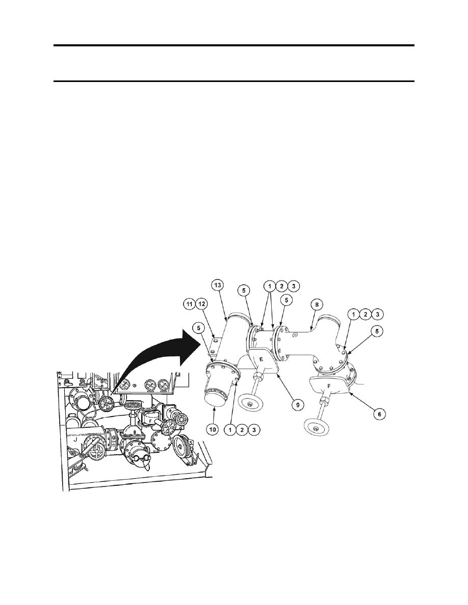
FLANGE MANIFOLD REMOVAL
1. Remove 8 screws (3), self-locking nuts (1), washers (2), gasket (5), and roadside bottom load adapter
(10) from flange manifold (13). Discard self-locking nuts and gaskets.
2. Remove 8 screws (3), self-locking nuts (1), washers (2), and gasket (5) from E valve (6). Discard self-
locking nuts and gaskets.
3. Remove 2 screws (11) and self-locking nuts (12) from cabinet frame. Discard self-locking nuts.
4. Remove piping clamp and flange manifold (13).
FLANGE MANIFOLD INSTALLATION
1. Install flange manifold (13) and piping clamp.
2. Install 2 screws (11) and new self-locking nuts (12) to cabinet frame.
3. Install new gasket (5), 8 screws (3), washers (2), and new self-locking nuts (1) to E valve (6).
4. Install new gasket (5), roadside bottom load adapter (10), 8 screws (3), washers (2), and new self-
locking nuts (1), to flange manifold (13).
0132 00-2
|
||
|
||


