
| Tweet |

Custom Search
|
|

|
||
 TM 9-2330-329-14&P
4-INCH PUMP MAINTENANCE--Continued
0146 00
DISASSEMBLY
NOTE
Measure and record thickness of gasket(s) for ease
of assembly.
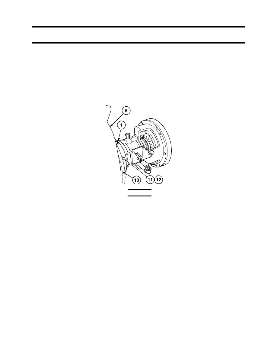
1.
Remove eight nuts (11), lockwashers (12), intermediate housing (1), and gasket(s) (13) from
pump (6) as an assembly. Discard lockwashers and gasket(s).
WARNING
The spring load on mechanical seal may cause impeller to
fly off shaft while being removed, causing serious injury
to personnel.
2.
Remove impeller (21) from impeller shaft (33) by unscrewing it in the same direction as pump turns.
3.
Remove seal plate (25), mechanical seal (24), spring seat (23), and shims (22) from impeller shaft
(33). Discard mechanical seal.
NOTE
If there are shims between bearing cap and bearing, set
aside for use at assembly.
4.
Remove four screws (38), lockwashers (37), bearing cap (28), gasket (29), and shims (30).
Discard lockwashers and gasket.
5.
Remove pump coupling (36) and key (34) from impeller shaft (33).
6.
Remove impeller shaft (33) and bearings (32) from intermediate housing (1) as an assembly by
using a soft hammer to hit the keyed end of the impeller shaft.
7.
Remove seal (35) from intermediate housing (1). Discard seal.
0146 00-4
|
||
|
||


