
| Tweet |

Custom Search
|
|

|
||
 TM 9-2320-279-10-3
Operation Under Usual Conditions (Cont)
714p
30
13
29
28
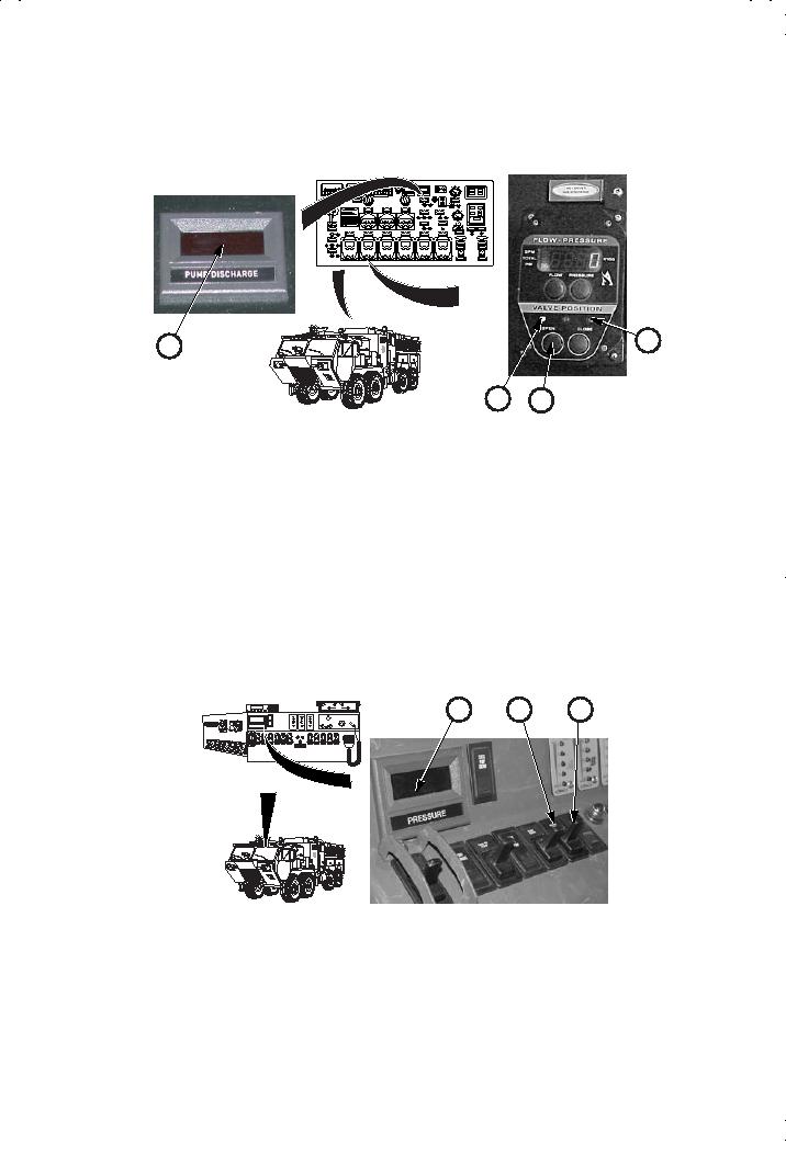
ad. Let pressure build up to 50 psi (345 kPa) on PUMP DISCHARGE
gage (13). Put NO. 1 DRIVER SIDE DISCHARGE valve control (28)
to ON position. Indicator light (29) will come on.
ae. Let pressure drop to zero. Put NO. 1 DRIVER SIDE DISCHARGE
valve control (28) in OFF position. Indicator light (30) will come on.
af.
Repeat steps ad. and ae.
ag. Install cap (26) on NO. 1 DRIVER SIDE DISCHARGE (27).
ah. Repeat steps ac. through ag. for NO. 2, NO. 3, and NO. 4 SIDE
DISCHARGES.
RADIO1
AUTO
18
31
32
RADIO
TALK
LISTEN
RADIO2
BOTH
INTERCOM
SQUELCH
VOLUME
A
B
2168
ai. Let pressure build up to 50 psi (345 kPa) on pump PRESSURE gage (18).
Put PUMP COOLER switch (31) in open position. Indicator light (32) will
come on.
aj. Let pressure drop to zero. Put PUMP COOLER switch (31) in closed
position. Check that indicator light (32) goes out.
2-211
|
||
|
||


