TM 10-4930-251-12&P
(4) Assembly.
(a)
Install O-ring, packing ( 15) on service adapter ( 14) and insert into fuel
manifold
(6). Install screws
(13). See Figure 4-17.
(b)
Attach
lanyard (17) with screw at lower left corner position,
and install
cap
16) on service
adapter
( 14).
(5)
Installation.
(a)
Position
fuel manifold
(1-2) within
control
box assembly
frarne mount (6) and
instal flat washer ( 10), screen (9), lock washer (8) and nuts
(7)/ . Torque to 50-55 ft. lbs.
(b)
Make sure iaskets ( 18) are in place. Guide tank hoses (4 and 5) Into place
onto fuel manifold.
Close earn lock handles (3). See Figure 4-17.
c.
Control
Box
Assembly
Maintenance.
(1 )
Removal.
(a)
Loosen nuts (1) to disconnect cables (2) from the adjustable bolt (3)). See
Figure 4-14.
(b)
Remove the nuts (1) and withdraw
cables (2) through bushing (4). See Figure
4-14.
(C)
Pull out on earn lock handles (3) at Fuel manifold
( 12). See Figure 4-17.
(d)
Disconnect
hoses (4) and (5). See Figure 4-17.
(e)
Ensure that the fuel dispensing
hose and nozzle are not connected
to the fuel
manifold
bottom
loading
port.
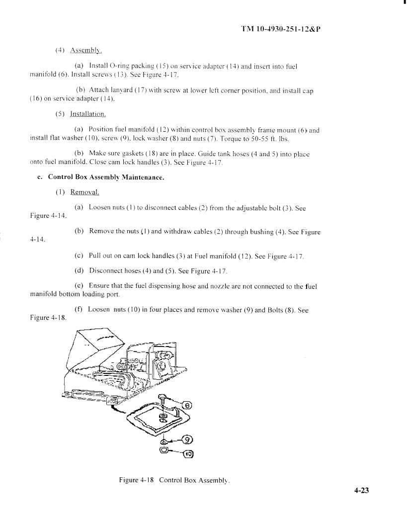
(f)
Loosen
nuts (10) in four places and remove
washer(9) and Bolts (8). See
Figure
4-18.
7 n-t
Figure 4-18
Control
Box Assembly.
4-23
|
|