TM 10-4930-251-12&P
(4) Assembly.
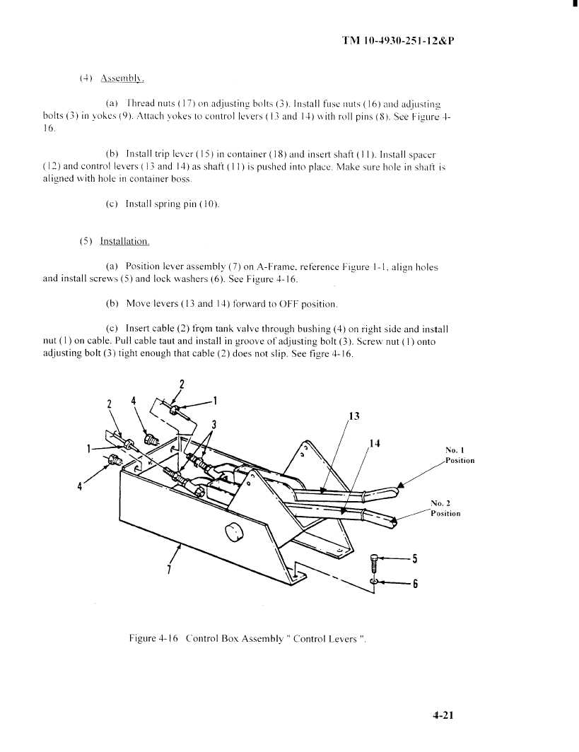
(a) Thread nuts ( 17) on adjusting, bolts (3). Install fuse nuts ( 16) and adjusting
bolts (3) in yokes (9). Attach yokes to control levers ( 13 ) and 14) with
roll pins (8). See FIigure 4
16.
(b)
Install
trip lever
( 15)
in container
( 18) and insert
shaft
(11 ). Install
spacer
12) and control levers ( 13 and 14) as shaft ( ) is pushed into place. Make sure hole in shaft is
aligned with hole in container boss.
(c)
Install spring pin (10).
(5)
Installation.
(a)
Position lever assembly (7) on A-Frarne,
reference Figure 1-
1, align holes
and install screws (5) and lock washers (6). See Figure 4-16.
(b)
Move levers (13 and 14) forward to OFF position.
(c)
Insert cable (2) from tank valve through bushing (4) on right side and install
nut ( 1) on cable. Pull cable taut and install
in groove of adjusting bolt (3). Screw nut
I
Onto
adjusting bolt (3)) tight enough that cable (2) does not slip. See figure4-16.
2
13
14
No. I
Position
No. 2
Position
6
Figure 4-16
Control Box Assembly
Control
Levers
4-21
|
|