TM 10-4930-251-12&P
13
18
14
100
19
20
14
TANK SKID
FEMALE END
14
25
0
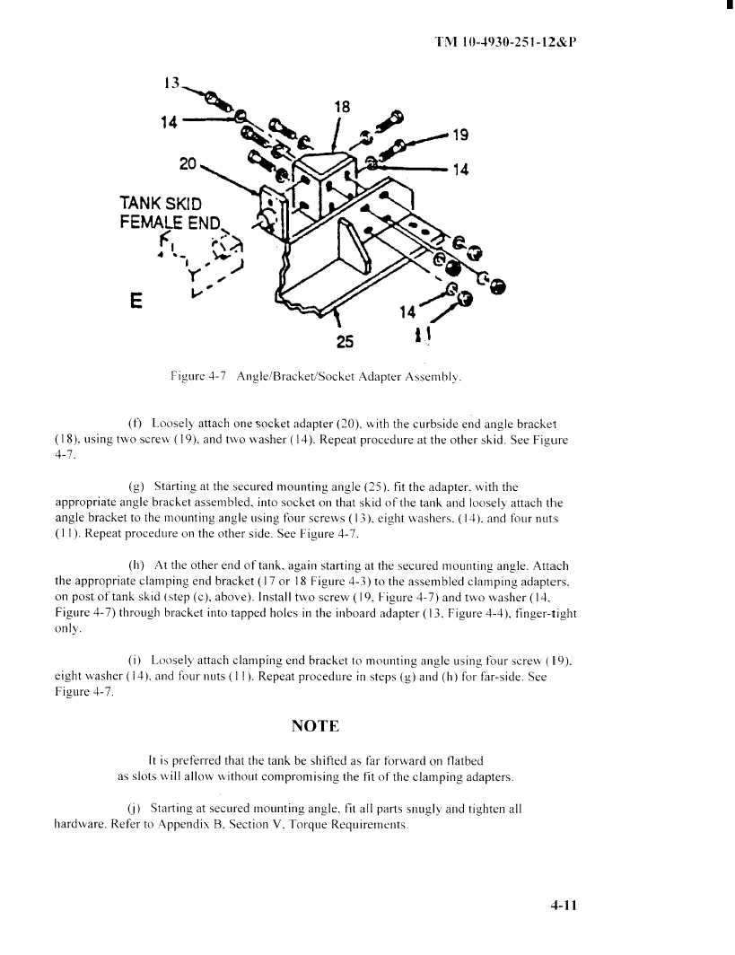
Figure 4-7
Angle/Bracket/Socket
Adapter Assembly.
(f)
Loosely attach one socket adapter (20), with the curbside end angle bracket
using two screw ( 19), and two washer (14). Repeat procedure at the other skid. See Figure
4-7.
(g)
Starting at the secured mounting angle (25), fit the adapter, with the
appropriate
angle bracket assembled, into socket on that skid of the tank and loosely attach the
angle bracket to the mounting
angle using four screws ( 13), eight washers, ( 14), and four nuts
(11). Repeat procedure on the other side. See Figure 4-7.
(h)
At the other end of tank, again starting at the secured Mounting
angle. Attach
the appropriate
clamping
end bracket ( 17 or 18 Figure 4-3)) to the assembled clamping
adapters,
on post of tank skid (step (c), above). Install two screw ( 19, Figure 4-7) and two washer ( 14,
Figure 4-7) through
bracket into tapped holes in the inboard
adapter ( 13),Figure 4-4), finger-tight
only.
(i)
Loosely
attach clamping
end bracket to mounting
angle using four screw, ( 19).
eight washer ( 14), and four nuts ( 11 ). Repeat procedure
in steps
and (h) for far-side.
See
Figure
4-7.
NOTE
It is preferred
that the tank be shifted
as far forward
on flatbed
as slots will
allow
without
compromising
the fit of the clamping
adapters.
Starting
at secured mounting
angle, fit all parts snugly
and tighten
all
hardware.
Refer to Appendix
B, Section V, Torque
Requirements.
4-11
|
|