
| Tweet |

Custom Search
|
|

|
||
 TB 9-2330-337-14
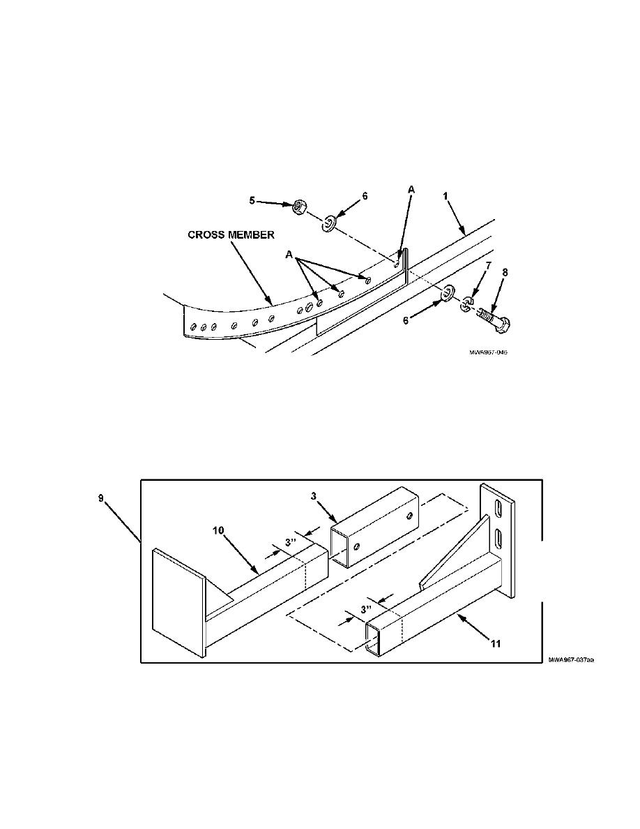
INSTALLATION (continued)
5. Using a 19/32- inch drill bit and cross member as a template, drill four holes, marked A, through the
center support bracket assembly (1), as shown.
6. Install center support bracket assembly (1) on cross member with four flat washers (6), two hexagon head
capscrews (8), lockwashers (7), and self-locking nuts (5). Hand tighten self- locking nuts.
7. Scribe a locating mark 3-inches (8 cm) from end of support bracket (10) and support bracket (11), as
shown. These marks will be used to position the slider support bracket (3).
8. Install support bracket (10) and support bracket (11) on slider support bracket (3) to form the left front
bracket assembly (9) , as shown.
4-5
|
||
|
||


