
| Tweet |

Custom Search
|
|

|
||
 TB 9-2330-336-14
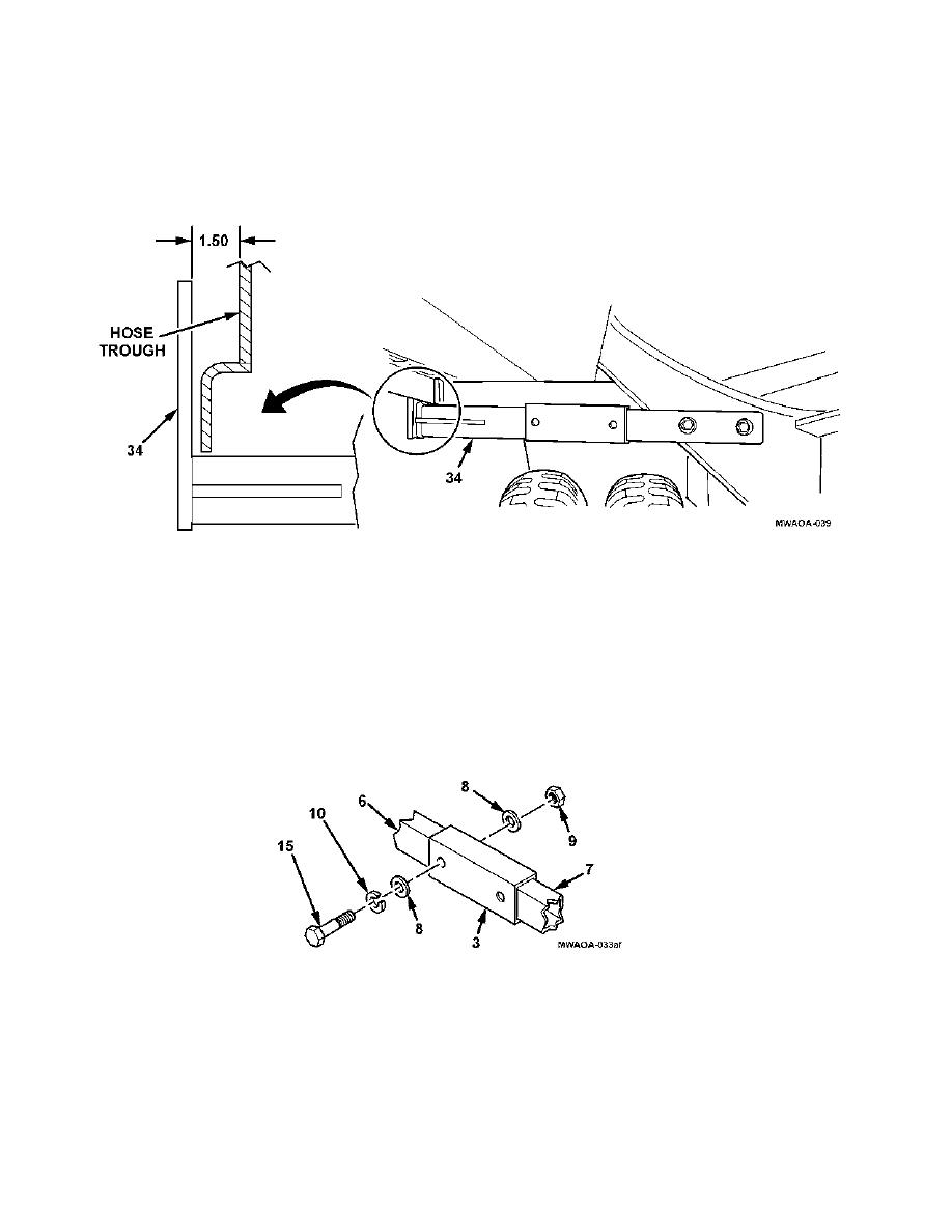
INSTALLATION (continued)
89. Adjust right rear bracket assembly (34) to ensure there is a 1.50-inch (38.1 mm) clearance between foot of
bracket and hose trough and clamp in place securely.
90. Align slider support bracket (3) with scribed mark on rear support bracket (7) or rear support bracket (6)
and clamp in place securely.
91. Using a 19/32- inch drill bit and slider support bracket (3) as a template, drill through holes through rear
support bracket (7) and rear support bracket (6).
92. Install four flat washers (8), two hexagon head capscrews (15), lockwashers (10), and self-locking nuts
(9) through slider support bracket (3), rear support bracket (7), and rear support bracket (6), as shown.
4-28
|
||
|
||


