
| Tweet |

Custom Search
|
|

|
||
 TB 9-2330-336-14
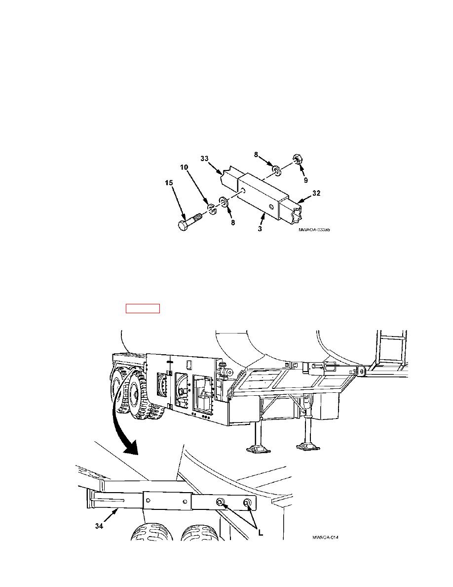
INSTALLATION (continued)
72. Align slider support bracket (3) with scribed mark on support bracket (33) or front support bracket (32)
and clamp in pla ce securely.
73. Using a 19/32- inch drill bit and slider support bracket (3) as a template, drill holes through rear support
bracket (33) and rear support bracket (32).
74. Install four flat washers (8), two hexagon head capscrews (15), lockwashers (10), and self-locking nuts
(9) through slider support bracket (3), support bracket (32), or front support bracket (33), as shown.
75. Position right rear bracket assembly (34) on vehicle frame and clamp in place.
76. Using a 19/32- inch drill bit and right rear bracket assembly (34) as a template, drill two holes, marked L,
through vehicle frame member.
77. Remove all burrs and sharp edges. Finish all exposed metal areas using a rust inhibitor primer and paint
as specified in Table 7-4, Materials and Parts. Allow for the appropriate time for primer and paint to cure.
4-23
|
||
|
||


