
| Tweet |

Custom Search
|
|

|
||
 TB 9-2330-336-14
INSTALLATION (continued)
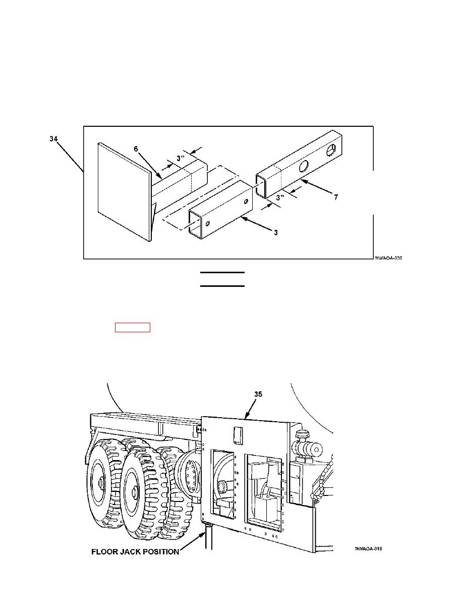
48. Scribe a locating mark 3-inches (8 cm) from end of support bracket (7) and support bracket (6), as
shown. These marks will be used to position the slider support bracket (3).
49. Install support bracket (7) and support bracket (6) on slider support bracket (3) to form right rear bracket
assembly (34), as shown.
WARNING
Use caution when lifting the supplemental armor. A swinging or shifting
load my cause injury to personnel.
50. Using dawg grips (Table 7-2), a suitable lifting sling, and lifting device, raise and position frame plate
(35) against engine and pump frame.
51. Place a floor jack at the rear of frame plate (35), as shown, to lift and hold the plate level and flush with
the bottom of the engine and pump frame. Clamp frame plate (35) in place on engine and pump frame.
4-16
|
||
|
||


