
| Tweet |

Custom Search
|
|

|
||
 TB 9-2330-329-14&P-1
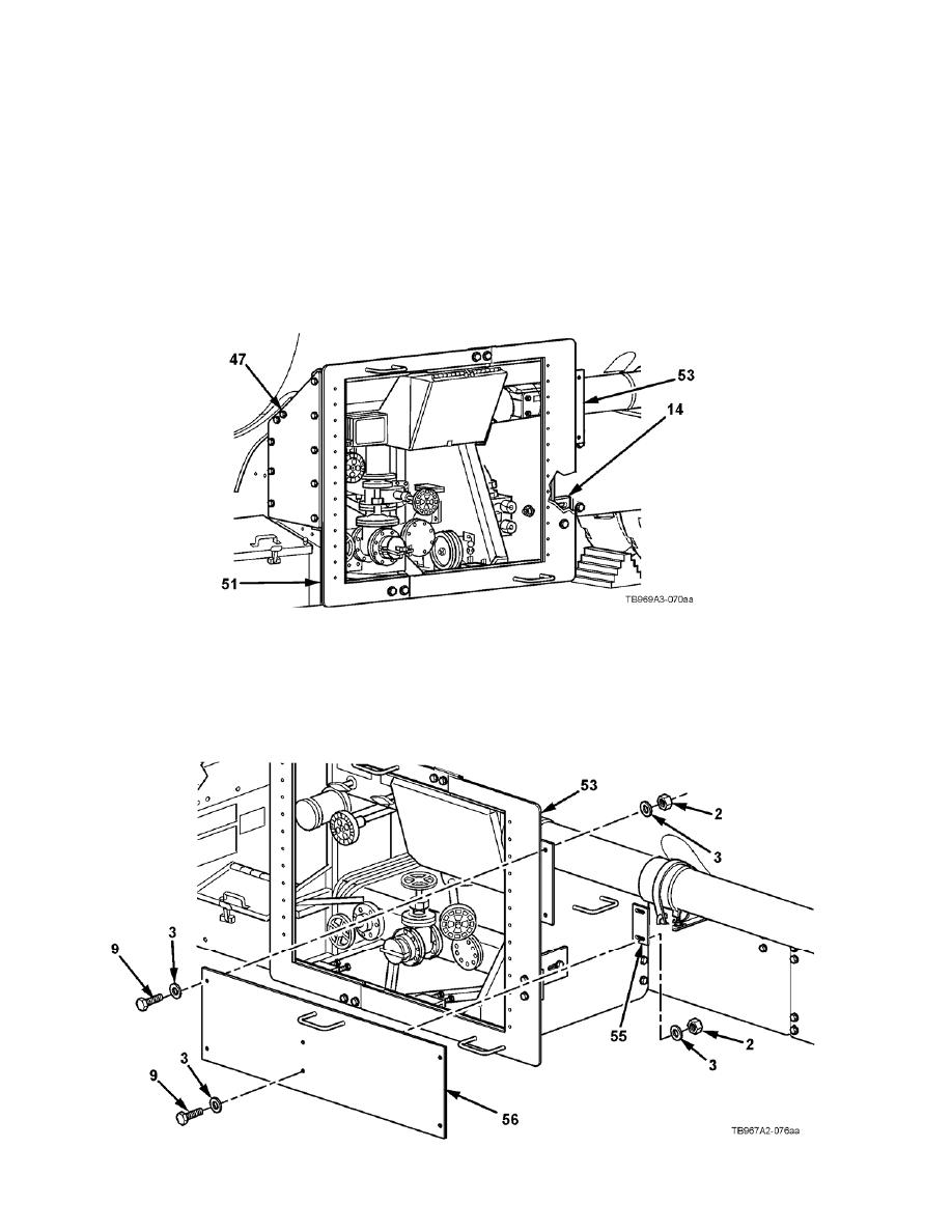
INITIAL INSTALLATION (continued)
70. Push front left door frame (51) back and hold in place while capscrews in slotted holes of
support plate (47) are tightened.
71. Tighten all support plate (47) hardware. Torque self-locking nuts to 55-65 lb-ft (75-88 Nm).
72. Tighten all front right door frame (53) and front left door frame (51) hardware. Torque
capscrews and self-locking nuts to 55-65 lb-ft (75-88 Nm)
73. Tighten all angle brace (14) hardware. Torque self-locking nuts to 55-65 lb-ft (75-88 Nm).
74. Position front fender panel (56) on front right door frame (53). Align holes of front fender panel
(55) with holes in front right door frame (53) and install with four flat washers (3), two capscrews
(9) and two self-locking nuts (2). Do not fully tighten hardware.
75. Install front fender panel (56) on tube canister bracket (55) with four flat washers (3), two
capscrews (9), and two self-locking nuts (2). Do not fully tighten hardware.
4-26
|
||
|
||


